20XX PROFESSIONAL MULTICOPTER MOTORS

20XX MULTICOPTER MOTORS QUICK LOOK:
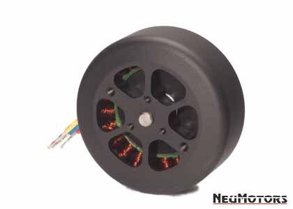
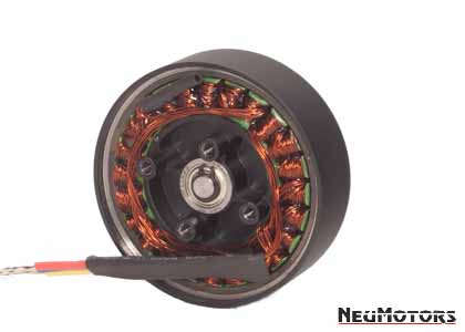
Neumotors 2000 series outrunner motors are professional / military grade multicopter motors. Our experience with numerous production UAVs and top aerospace manufacturers ensures 20xx series motors are the truly the best drives in their class.
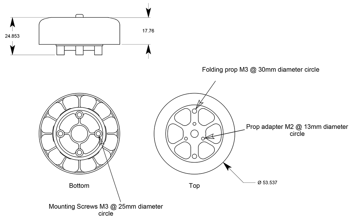
2025 motors weigh in at 3.35oz and feature high quality NSK bearings and internal cooling fans. Magnets are N42SH grade and winding insulation is rated for over 300F. Motors support multiple propeller mounting options.
-
-
- 53.5mm OD
- outrunner construction
- 6mm shaft
- Integral prop mounting hub
- 26 poles / 24 slots
- 20,000 max rpm
- US component sourcing and assembly available
-


20xx SERIES LENGTH AND POWER RANGE
Watts*
Watts*
Length
*Prices:
Prices subject to change without warning due to possible imposition of tarriffs.
ALL ORDERS PLACED AFTER MAY 1, 2025, ARE SUBJECT TO A 20% TARIFF SURCHARGE.
MOTOR KV:
The motor sizes and KVs listed above are the most common for this particular motor range. Custom sizes and KV (RPMs per volt) are usually available. Please contact us for more details if you don't immediately see the solution you are seeking in the tables above.
KV is the term used in the brushless motor workspace to specify the number of rotations per minute that a motor will turn for each volt applied to the motor/ESC with no load on the motor.
Neutronics specifications are +/- 5%.
For a more complete discussion of KV, please go to our KV FAQ page.
MOTOR Io @ 10V:
The no load current of a brushless motor is defined as the current the motor draws, with no load applied, at a specific voltage. The no load current is measured in Amps and denoted “Io.” Neumotors measures Io amperage at 10v DC input to speed controller.
MOTOR RESISTANCE:
The resistance of a brushless motor is the leg to leg resistance of the stator, measured in ohms. The value listed in the motor's data sheet is typically the resistance at room temperature (22°C).
POWER RATINGS (Watts):
- Continuous rating is the power the motor can deliver while maintaining the external housing temperatures below 100C.
- MAX power is achieved at max RPMs and voltage, not at a partial throttle or reduced voltage.
- MAX power rating is the power the motor can deliver beginning with motor at a temp of 20C until it reaches it's limit temperature of 100C.
- The ratings are therefore dependent on a number of variables including air flow, ambient air temperature, contact cooling etc. Each application will present different variables.
MTBF RATINGS:
When used within the constraints described above, BLDC motors' primary "wear" item(s) are the bearings supporting the shaft. Bearing life is inversely affected by speed, temperature, and radial and axial loads. While an MTBF figure can be generated, it would be rendered invalid by excursions beyond prescribed temperatures or load limits - such as prop strikes, or side loads. MTBF must be determined on a case by case basis, and even then, it would be subject to numerous exceptions.
MAX VOLTAGE
Max voltage is limited by the following concerns:
1. Mechanical redline. The motor should not be driven faster than the mechanical limits of the motor which is determined as Kv (RPMs per volt) times the applied voltage. Max voltage must be kept below the voltage which will spin the motor over max rpm for the motor series.
2. In some cases, usually where the Kv is very low, voltage times Kv is under the mechanical redline. In these cases, the insulation of the winding wire must be considered. Our standard winding is safe up to 130V. We hi-pot test all standard-wind motors at 300V. We offer a high voltage winding for use up to 450 volts. We can also build motors for voltages beyond 450 volts, please contact us for more information.
MAX AMPERAGE
See power ratings above.
COMPONENT SPECIFICATIONS
- Winding max temperature: 180C
- Magnet max temp: 150C or higher
- Bearings: Japanese SPB bearings
CONTROLLER SETTINGS: TIMING
- APD controllers automatically adjust timing for optimum efficiency
- Recommend low timing for controllers that require configuration
POLE COUNT vs. POLE PAIRS
- Neumotors lists the number of poles in a motor rotor. Example: N S N S would be a four pole motor.
- Some ESC manufacturers use the term "pole pairs" which refers to the number of N and S pairs. Example: N S N S would be a 2 pole-pair motor.
Neumotors Naming Convention Details
NOTE: Innrunners use imperial dimensions (inches), outrunners use metric dimensions (mm).
Using the 1530/.75D (2640 KV) as our example: 1530/.75D (2640 KV) should be read as 15 | 30 | .75 | D which runs at 2,640 RPMS per volt.
1530/.75D (2640 KV)
The last part of the code - the Kv, is the voltage constant.* It represents the number of RPMs the motor will spin for each volt applied to the motor by the speed control. A 1,000 KV motor should spin at 10,000 RPMs when 10 volts are applied to an unloaded motor (10 x 1,000 = 10,000).
The Kv of a particular motor size is determined by the number of turns of wire around the stator teeth. The length of the motor and the type of wire termination inside the motor also determine the motor Kv.
*Kv in this context does not mean kilovolt. We aren't working with kilovolts here!!
1530/.75D (2640 KV)
The first two digits are the motor's internal diameter in inches. 15 = 1.5" inches - so all 15 series are the same internal diameter.
1530/.75D (2640 KV)
The second two digits represent the motor's internal length, the stator stack, specifically. 30 is 3.0 inches - so a 1530 is 3 inches long inside and a 1539 is 3.9 inches long inside the case. Longer motors have more power capability and more weight.
1530/.75D (2640 KV)
The 3rd set of digits is the number of times the internal wires are wrapped around the stator teeth. 1530/.75D has .75 wraps of the wire inside the motor around the steel teeth of the stator.
1530/.75D (2640 KV)
The final letter refers to the internal connection of the 3 motor wires. D = Delta, the Greek letter for D that looks like a triangle. The other option is Y, and the Y wind looks like a letter Y on a wiring diagram. A Delta motor will spin 1.8 times the Kv of a Y motor with the same number of turns. Change the turns in a Y motor and it will spin just as fast as a Delta with nearly identical performance.
NOTE: This system applies to the NEUMOTORS INRUNNERS. OUTRUNNERS are the same format, but they are in metric units (MM).
